Sensing Devices

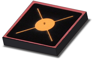
TASC has mastered silicon-based and compound semiconductor epitaxy technology. We also offer professional design and chip fabrication. These are combined with robust quality control to create world-class sensing components, including a variety of photo-sensing component solutions.
such as photodiodes, phototransistors, photo-sensing controllable thyristors, and Zener diodes used in everyday applications such as wearable health management, industrial, automotive, and home appliance products.

Mechanism

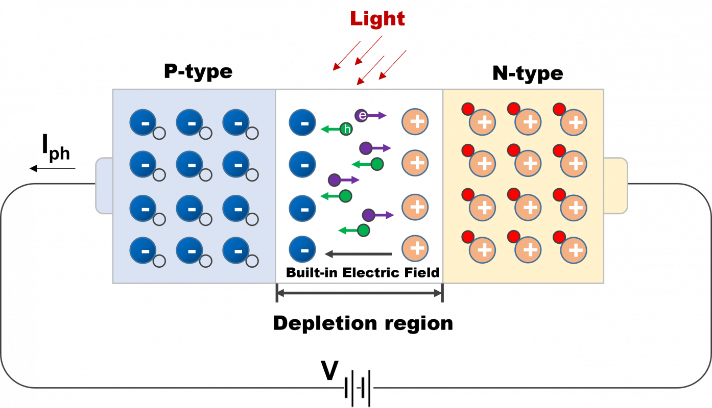
When an equipped with enough energy photon hit the photodiode and the absorption occurs in the depletion region, the built-in electric field will make the electron-hole pair move toward the anode and the cathode to generate the photo current. In fact, the light signal is the sum of the photo current and dark current. Thus, the dark current regarded as a noise should be effectively reduced to increase the sensitivity on the device.

Device Structure

The photodiode is composed of PN junction. Inserting the intrinsic layer with high resistivity will form the PIN structure which increase the effective width of depletion layer. Apart from increasing the breakdown voltage, it also generates large amount of electron-hole pair to increase quantum efficiency. Moreover, it further reduces the junction capacitance to raise device switching speed.

Material selection

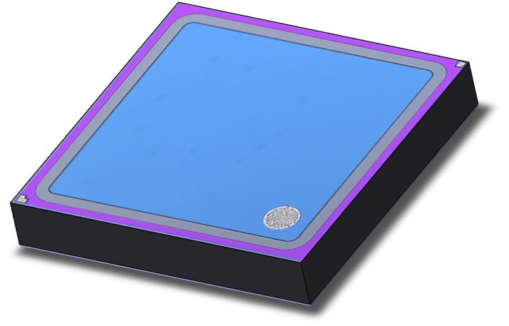
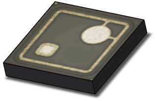
Because the photodiode is sensitive to particular wavelength range, so according to wavelength of light source, the corresponding materials will be chosen to do detection. The materials shown below :

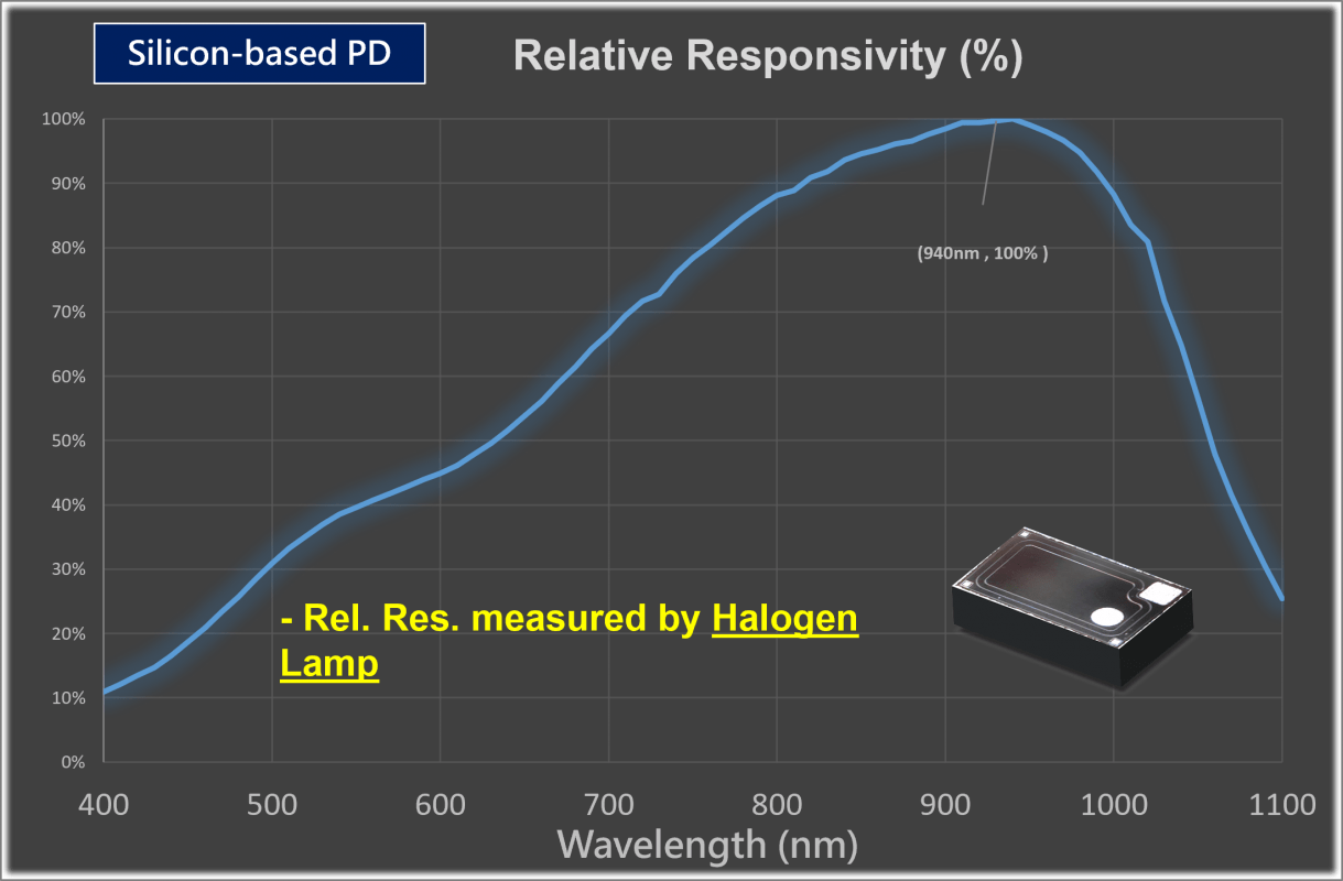
Silicon-based PD : Common sensing wavelength within 400~1100 nm
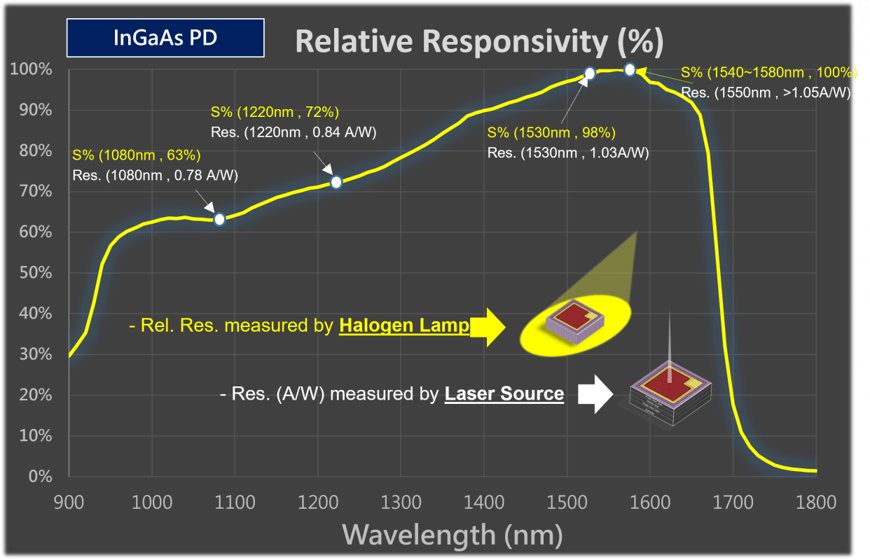
Compound PD : InGaAs PD, common sensing wavelength within 900~1700nm

Characteristics

Responsivity : The conversion efficiency between radiant optical power and the generated current ; The unit is Ampere/Watt (A/W), which can also be converted to quantum efficiency (%)
Dark current : The internal flowing current in the optical sensing device with no incident light environment ; The unit is nA
Breakdown Voltage : The minimum reverse bias voltage when diode reverse conducting
Responsivity spectrum : The line diagram of photocurrent conversion efficiency over different wavelength of incident light source. The light spectral shown as below :

Mechanism

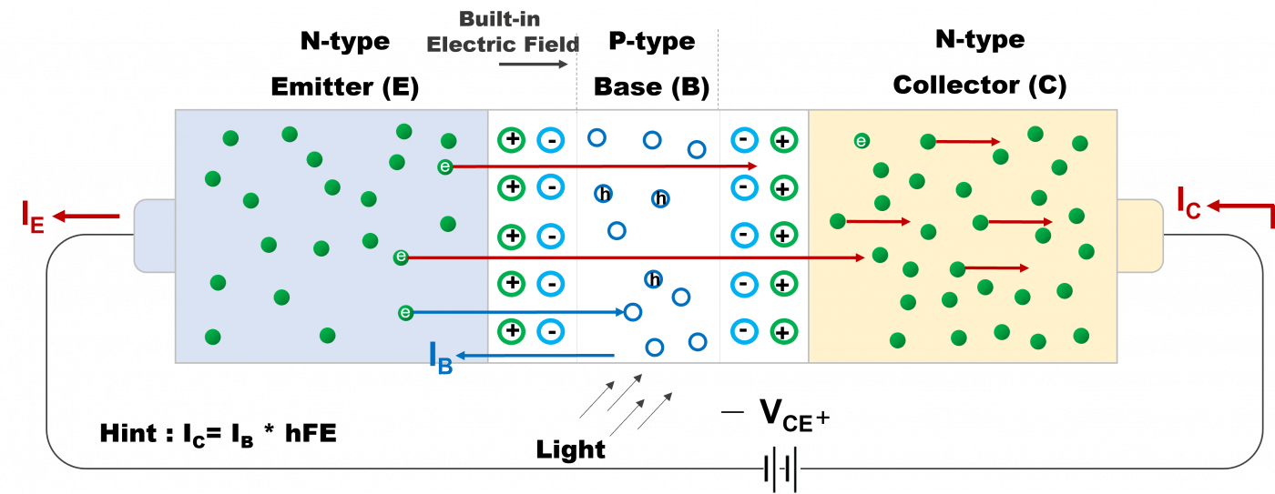
The phototransistor is a kind of NPN junction device which is similar to photodiode. When illumination, the photon will impact the base and act as a applied voltage to base (VBE). The emitter electron current flows to base and recombine with holes to generate the small current (IB) which is proportional to illumination of incident light. Besides, because the base thickness is generally thin, so the electron that flows from emitter to the base will diffuse to collector and is attracted by the forward voltage between collector-emitter. Therefore, the generated collector current (IC) will be amplified according to the current gain (hFE) of the phototransistor.

Device Type

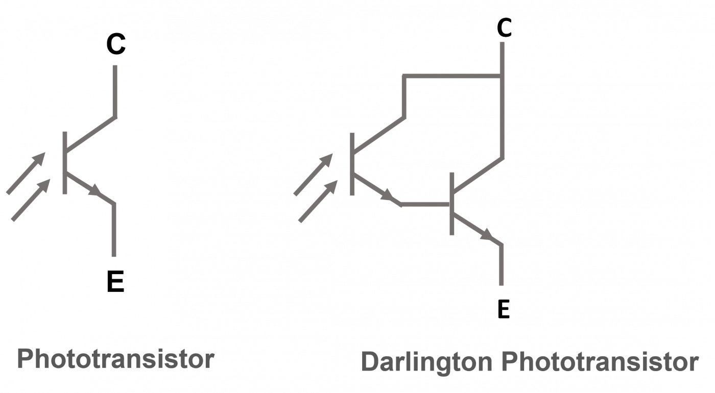
Phototransistor is mainly composed of NPN junction or two phototransistors form Darlington phototransistor in order to acquire the larger gain (hFE)

Characteristics

BVCEO : The minimum voltage makes collector-emitter junction collapse when base is open circuit
BVECO : The minimum voltage makes emitter-collector junction collapse when base is open circuit
ICEO : The leakage current flowing to collector-emitter when base is open circuit with no illumination
VCE(S) : The maximum voltage of collector-emitter makes the PN junction forward biasing
hFE : The amplified current gain between collector current and the generated photo current in the base

The phototransistor in photocoupler

1. It contains the light emitted, light received and signal amplified to accomplish the electric-light-electric conversion
2. The input the output completely achieve the electrical isolation with one-way transmission and the output signal has no influence on input
3. The current transfer ratio is defined as the ratio of output current (IC) to input current (IF). It mainly estimates the load resistance (RL) selection
4. Commonly apply to signal isolation switch and signal transmission

Mechanism

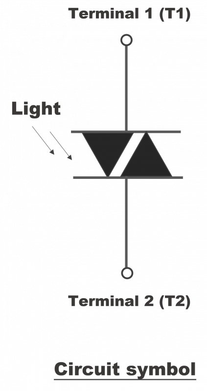
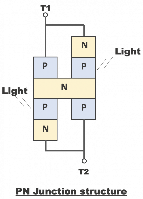
The phototriac is regarded as a pair of PNPN junction (Similar to Darlington phototransistor operation) in reverse parallel connection with two electrodes of T1 and T2. When the control gate is triggered after light illumination, it will make the phototriac conducted no matter what the polarity voltage applied to the T1 & T2.

Operation Type

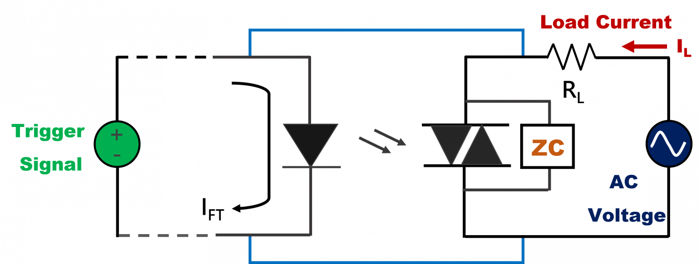
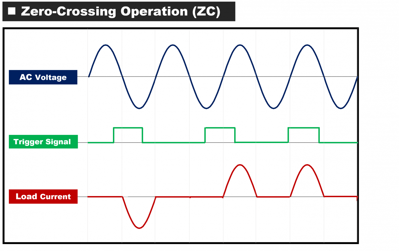
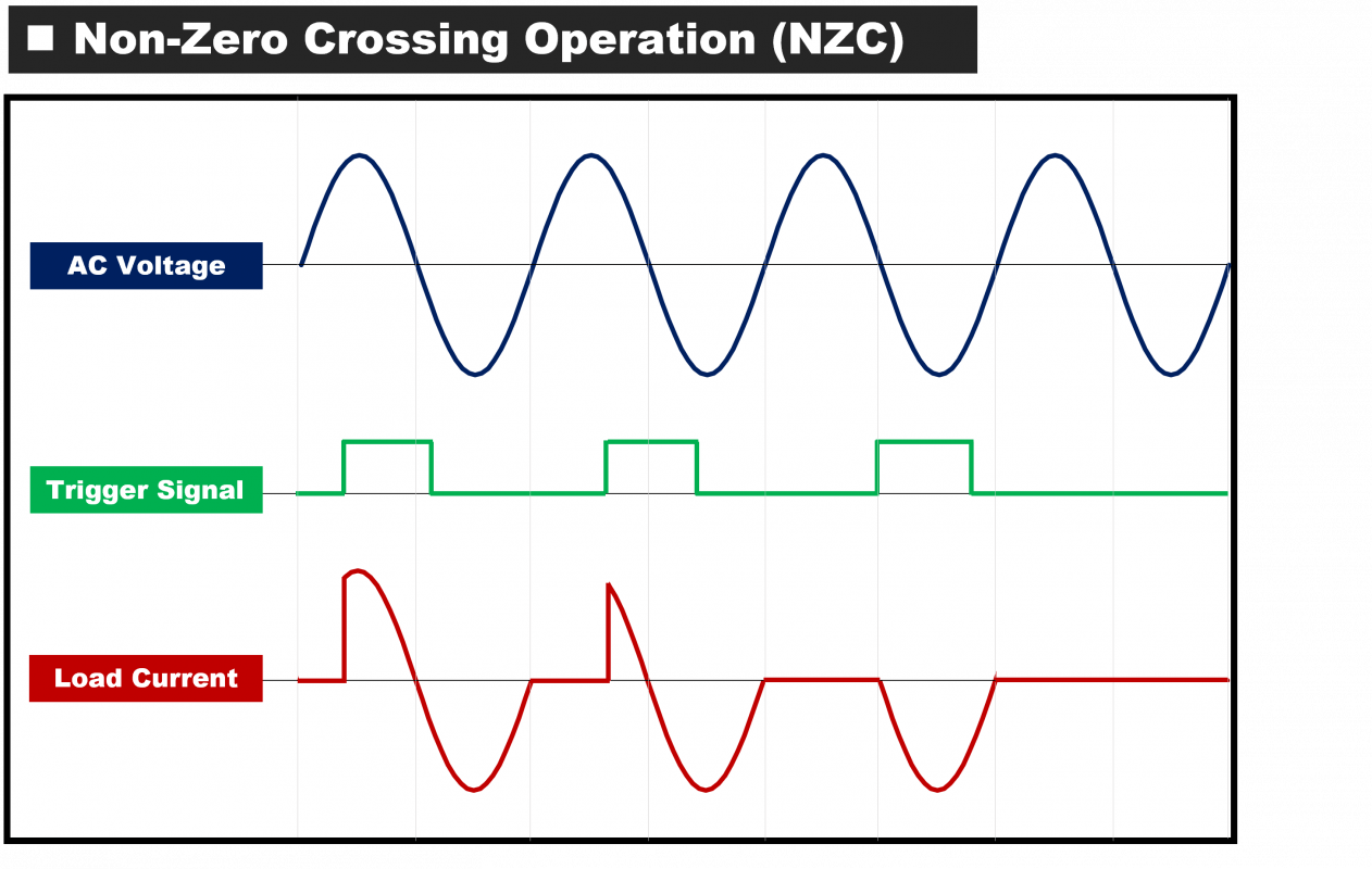
1. Zero-Crossing (ZC):

For 60Hz AC power supply, there are sixty sine wave cycles and sixty crossing points to zero voltage. When turning on or switching off at this moment, it doesn’t quite occur the sparkle in order to extend the life of switch connection node.
If using the light triggering thyristor with much shorter conducting time characteristics as a control switch which drives external connection node at the zero crossing, it is able to surpass those of longer reaction time in conventional
electromagnetic relay which is unable to reach in the zero-cross switching

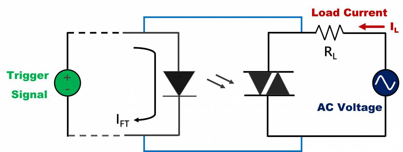
2. Non-zero crossing (NZC):

What differs from ZC is that the NZC allows to output voltage at any time of AC sine wave. Therefore, because the output voltage wave form is not always the competed sine wave so it can control the phase angle to output different power

Key Characteristics

Repetitive peak off-state voltage (VDRM) : A forward peak voltage that can be repetitively applied to the terminals in the conditions of control-gate open and phototriac forward blocking
Peak on-state voltage : The peak voltage across the device while it is on-state
dV/dt : The maximum value of rate of the rising voltage that can be applied across the terminals of the phototriac
Holding current (IH) : The minimum current level continues to keep the device conducting in the conditions of the specified environment temperature and no control gate current is applied
Inhibit Voltage (VINH) : When loading voltage is higher than inhibit voltage in the ZC circuit, it can prevent phototriac from triggering even though the trigger current is high

Power Devices

TASC not only provides products such as protection components and power products that are indispensable in various fields, but will continue to focus on components such as low-loss and high-voltage characteristics in the semiconductor field in the future. key role in the supply chain.

Mechanism

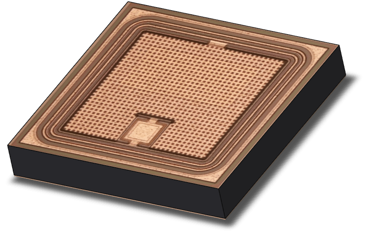
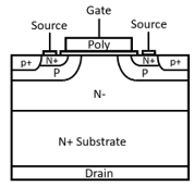
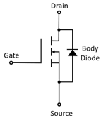
Vertical Double Diffused MOSFET is also called VD-MOSFET ;The distinguishing feature of VD-MOSFET is its vertical P-N junction structure, which gives it excellent voltage withstand capability and low resistance. In VD-MOSFET, charge is vertically diffused into the N-channel region and it can operate at lower drain voltages, making it an ideal choice for many high-power applications.

Main application

In addition to its high voltage withstand capability, VD-MOSFET also possesses fast switching characteristics, enabling efficient power conversion. During switching operations, VD-MOSFET can transit between high-resistance and low-resistance states in a very short time, thereby improving overall system efficiency. Furthermore, VD-MOSFET offers low static power consumption and high reliability, making it suitable for a wide range of applications.

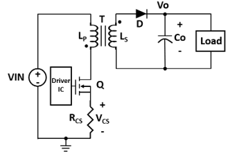
Power Converter

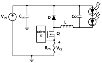
Lighting Control

The main applications of VD-MOSFET include power converters, lighting control, DC motor control, electronic locks, chargers, wireless chargers, and power factor correctors. In these applications, VD-MOSFET can provide efficient power conversion and reliability while meeting the requirements for high voltage and low resistance. As a result, it finds widespread use and favor in many high-power applications.

Key parameters for MOSFET application

When using MOSFETs, it is important to consider insulation, heat dissipation, electrostatic protection, and good circuit design. In designing MOSFET circuits, factors such as input power, load, and control circuits need to be considered to ensure the proper functioning of the entire system. Additionally, it is necessary to select and configure other electronic components such as diodes and capacitors appropriately. When using MOSFETs, it is necessary to understand their important parameters, such as:

  • Absolute Maximum Ratings :

– BVDSS (Drain-Source Breakdown Voltage) : Maximum breakdown voltage between drain and source.
– VGSS (Gate-Source Voltage) : Maximum driving voltage between gate and source.
– ID(max) (Continuous Drain current (max.) : Maximum continuous drain current.
– PD (Power Dissipation) : Maximum power dissipation of the MOSFET.
– Tj (Operating Junction Temperature) : Maximum operating junction temperature of the MOSFET.

  • Electricity Characteristic :

– RDS(on) (Drain to Source on Resistance) : On-resistance of the drain-source channel.
– IDSS (Drain to Source Leakage Current) : Leakage current between drain and source.
– IGSS (Gate to Source Leakage Current) : Leakage current between gate and source.
– Vth (Gate threshold Voltage) : MOSFET turn-on voltage or gate threshold voltage.
– VSD (Diode forward voltage drop) : Parasitic diode forward voltage drop.

  • Dynamic Parameters :

– Ciss (Input Capacitance) : Input power capacitance
The total capacitance of Cgs (gate-source capacitance) and Cgd (gate-drain capacitance).
– Coss (Output Capacitance) : Output power capacitance
The total capacitance of Cds (drain-source capacitance) and Cgd (gate-drain capacitance), and it represents all the capacitance on the output power side.
– Crss (Reverse Transfer Capacitance) : Feedback capacitance
Cgd (gate-drain capacitance)

  • Transfer Switch Parameters :

– Qg (Total Gate Charge):
The amount of gate charge required for the MOSFET to transit from 0V gate voltage to a certain voltage during operation, which is charged by Ciss (input capacitance).
– Qgs (Gate to Source Charge):
The amount of charge between the gate and source needed for the gate voltage to rise from 0V to a certain voltage, charged by the gate-to-source capacitance.
– Qgd (Gate to Drain Charge):
The amount of charge between the gate and drain needed for the drain-to-source voltage (VDS) to drop from the supply voltage to the on-state voltage, charged by the gate-to-drain capacitance.
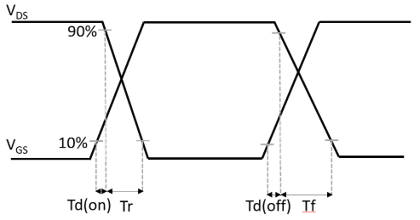
– Tr (Rising Time):
The time required for the drain-to-source voltage to decrease from 90% of the setting voltage to 10%.
– Td(on) (Turn On Delay Time):

The time from the gate-to-source voltage drops to 90% of the setting voltage to the drain-to-source voltage rises to 10% of the setting voltage.
– Tf (Falling Time):
The time required for the drain-to-source voltage to rise from 10% to 90% of the setting voltage.
– Td(off) (Turn Off Delay Time):
The time from the gate-to-source voltage drops to 90% of the setting voltage to the drain-to-source voltage rises to 10% of the setting voltage.

TVS Features

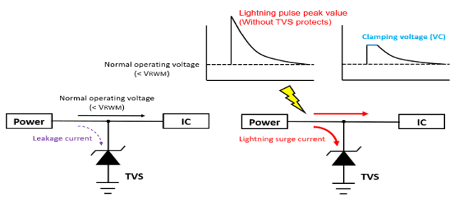
The working principle of a TVS diode is that within its normal operating voltage range, current can flow through the diode. However, when the voltage exceeds a certain threshold, it enters a low impedance state, guiding the excess current and reducing the overvoltage to a safe voltage range, thereby protecting electronic devices (e.g., ICs).

Here are its fundamental important characteristics

  • Fast response:

TVS can respond the transient voltage within nanoseconds and quickly share the overvoltage.

  • Low voltage leakage current:

TVS has very low leakage current under reverse voltage, thus not affecting the normal operation of the circuit.

  • High energy absorption capacity:

TVS can absorb high-energy transient voltage, making it suitable for various application environments.

  • High reliability:

TVS has a long lifespan, typically lasting millions of pulses, ensuring circuit stability and reliability.

Main application parameters of TVS

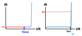
The selection of TVS should be based on factors such as the operating voltage, current, and protection level of the protected circuit. When choosing a TVS, it is necessary to understand the following main parameters:

  1. Reverse Working Maximum Voltage (VRWM)
  2. Reverse Breakdown Voltage (VBR)
  3. Clamping voltage (VC) at peak pulse current
  4. Reverse Current (IR)
  5. Junction capacitance (CJ), etc.

TVS Applications

TVS diodes are widely used in various electronic devices and circuits, primarily for protecting sensitive components and devices from the impact of high voltages. Here are the main applications of TVS diodes :

• Industrial and Consumer Electronics Power Protection (AC/DC) :
TVS diodes can be used to protect various types of power systems, including DC power supplies, AC power supplies, and chargers, to prevent them from being affected by high voltages.

• Communication Equipment Protection:
TVS diodes can be used to protect various types of communication equipment, including telephones, fax machines, modems, routers, etc., to prevent these devices from being affected by voltage surges from the external environment.

• Computer Equipment Protection :
TVS diodes can be used to protect computer equipment, including central processing units (CPUs), memory, hard drives, etc., from voltage surges originating from power sources or signal lines.

• Automotive Electronic Equipment Protection:
TVS diodes can be used to protect automotive electronic equipment, including engine control modules, electronic ignition systems, in-car audio systems, etc., from voltage surges originating from the vehicle’s electrical system.

• Industrial Control Equipment Protection:
TVS diodes can be used to protect various types of industrial control equipment, including programmable logic controllers (PLCs), variable frequency drivers, servo drivers, etc., from voltage surges originating from power sources or signal lines.

Zener Characteristics

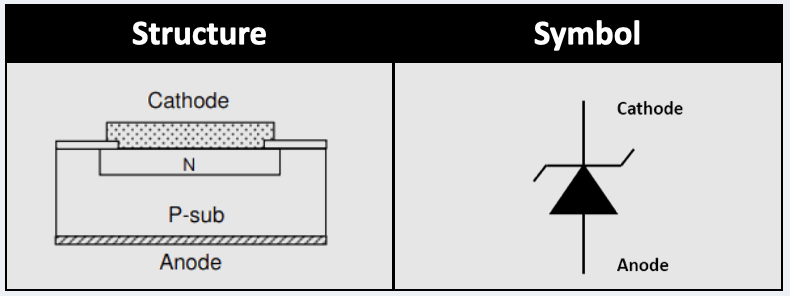
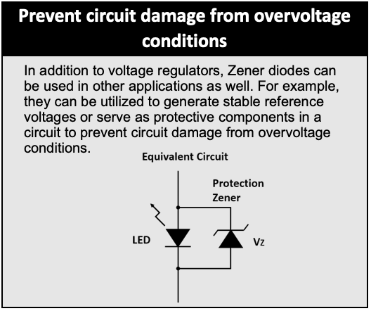
Zener diode is a semiconductor diode with special voltage stabilization characteristics. Typically, a diode conducts electricity under forward bias and blocks it under reverse bias. However, a Zener diode, under specific reverse bias conditions, begins to conduct and maintain a stable reverse voltage. This stable reverse voltage is known as the Zener voltage.

Zener Key Application Parameters

When using Zener diodes, it is important to consider their maximum power rating. This is because Zener diodes generate a significant amount of heat when conducting. If the power dissipation exceeds their maximum rating, they can overheat and become damaged. When selecting Zener diodes, it is crucial to understand the following key parameters:

  1. Zener Voltage (Vz): The desired stable reverse voltage value.
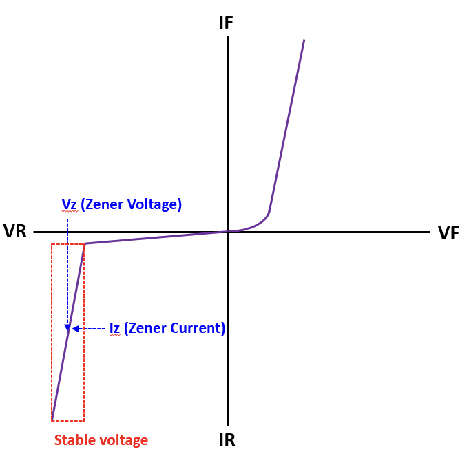
  2. Zener Current (Iz): The current flowing through the Zener diode.
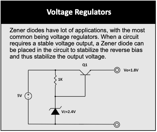
  3. Power Dissipation (Pd): Pd = Vz * Iz, which represents the power consumed by the Zener diode.

Zener Applications

Mechanism

Resistor is a passive component which the main function is to limit the current in a circuit;According to Ohm’s law, the following formula:

The Main Application

Resistors are mainly used in electronic circuits.

Application principle:

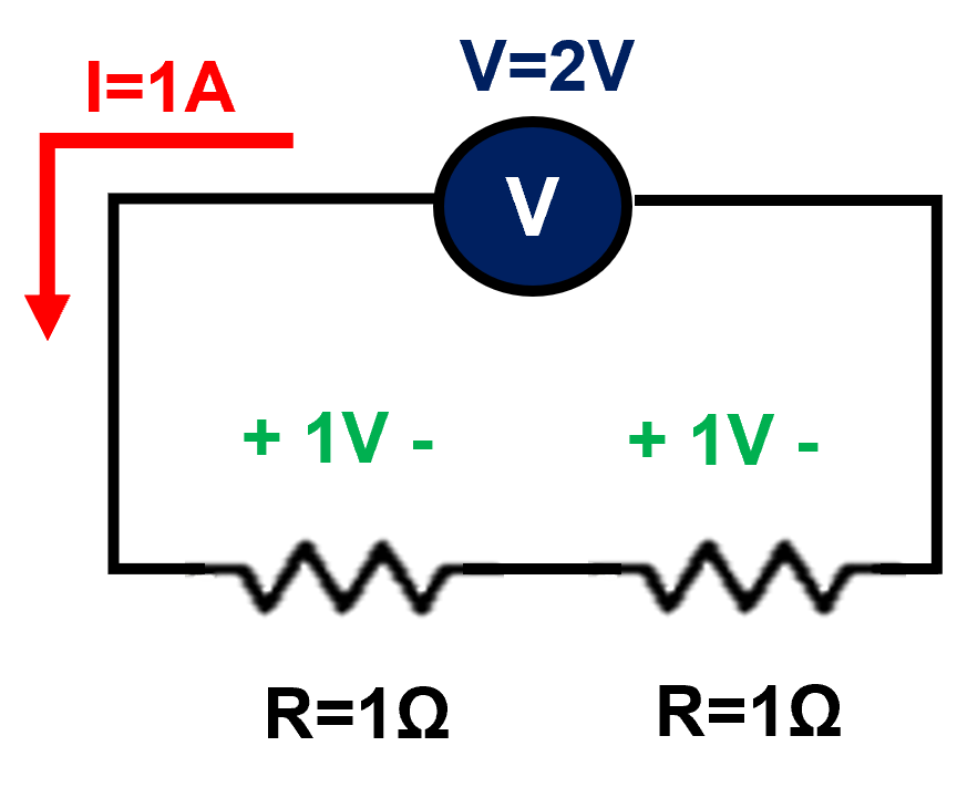
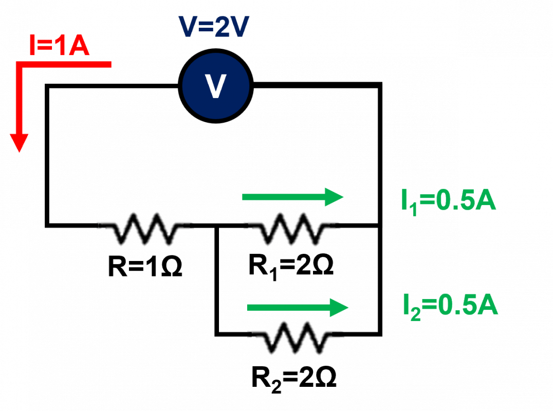
When the voltage in the electronic circuit is fixed (two-pins), the design of the resistor can provide a stable current drive for the circuit and prevent damaging the circuit from excessive current;and the resistor can also be used to adjust the voltage drop in the circuit, moreover the series and parallel circuit of resistor can achieve the function of dividing voltage and current.

Voltage Divided:

As shown in the figure on the right, when the voltage value of general electrical appliances is fixed, if the fixed voltage value of the electrical appliances is lower than the power supply, it is impossible to directly connect the electrical appliances to the power supply. Therefore, in this case, usually in order to divide the voltage, a resistor with an appropriate resistance is connected in series so that the electrical appliance can operate smoothly under a fixed voltage, and the application of the resistor in it is called “voltage Divider”.

Current Divided:

As shown in the figure on the left, If it is necessary to connect some different fixed current electrical appliances to the circuit at the same time, a resistor can be connected between the two ends of the relatively low fixed current electrical appliances through parallel circuit ,this application method is called “Current Divider”.

Emitting Devices

TASC strives to provide innovative and customized services. We use our mature chip fabrication technology to satisfy the needs of our global clients. We also offer a wide spectrum of lighting solutions including colored light, IR LED, and vertical-cavity surface-emitting lasers (VCSEL).The many applications include home appliance, lighting, industry, security & surveillance, display, automotive and consumer electronics, and more.

Mechanism

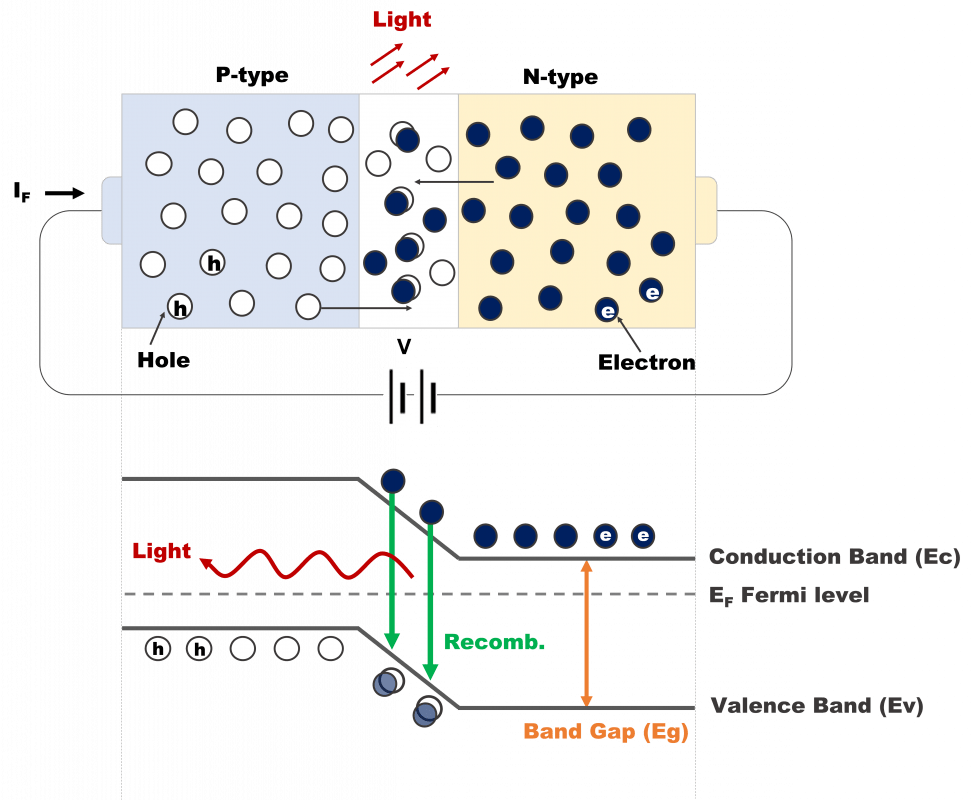
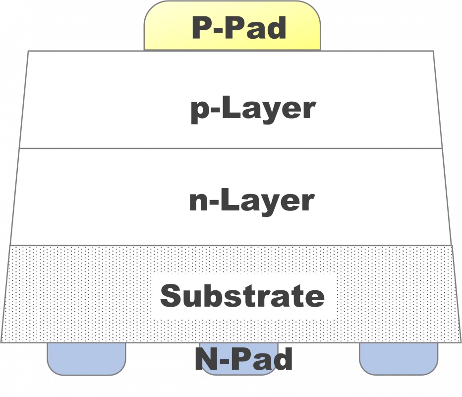
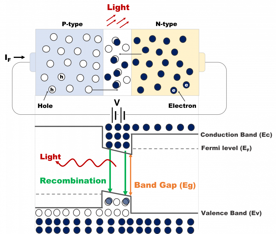
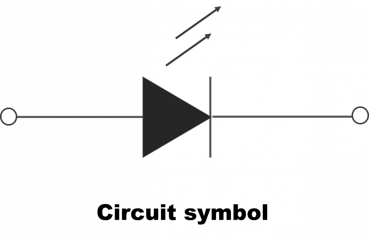
Most of the LED are direct band gap materials and mainly composed of P-type and N-type semiconductors. When a forward bias is externally applied, the holes and electrons flow to N-electrode and P-electrode by electrode field respectively. It will release a certain energy due to electrons and holes recombination at the PN junction. If the energy is released in the form of photons, it will produce the ultraviolet light, visible and infrared light according to different energy gap of materials.

General LED Series (TASC)

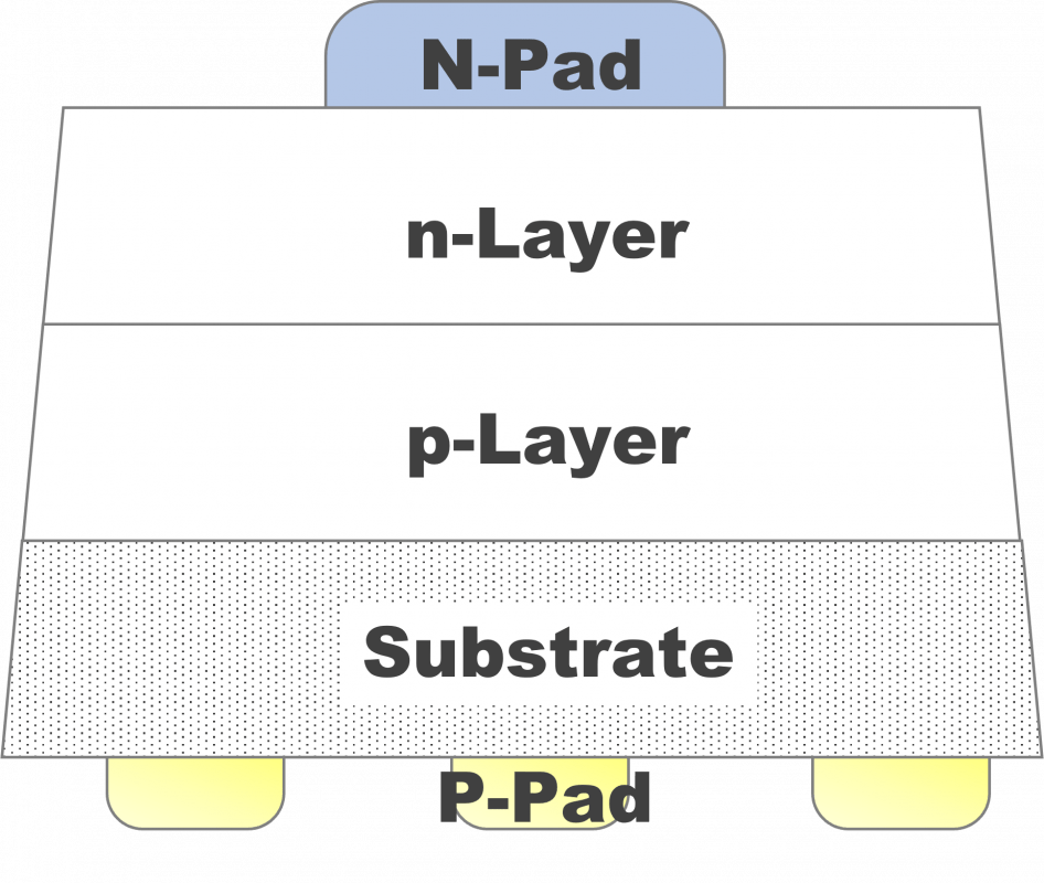
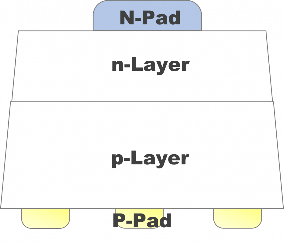
These types of epitaxy are produced by liquid phase epitaxy or vapor phase epitaxy. These kind of products have good uniformity in optical power (mW) and light intensity (cd) which can adapt to indoor products. Thus, the visible light is commonly used in small decoration lighting and indicator. The infrared light is for signal transmission in coupler and monitor.

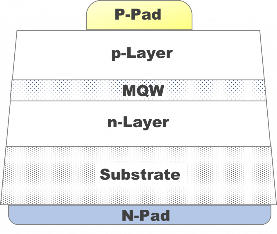
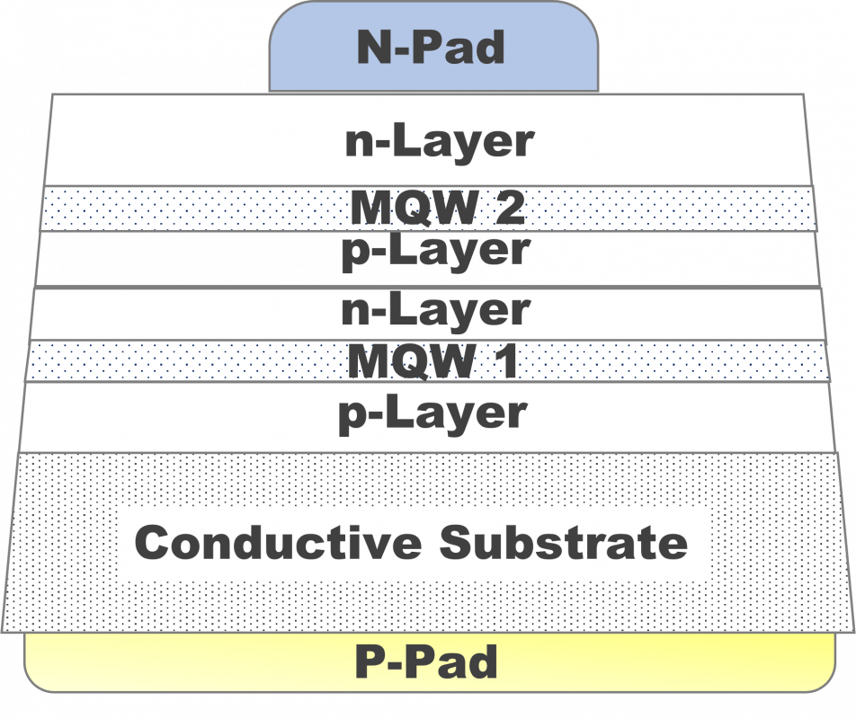
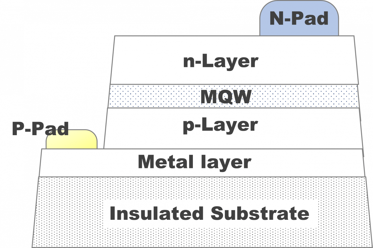
Chip structure

Structure (A)

Structure (B)

Structure (C)

Structure (D)

Parameters Explanation

Dominant wavelength (WLD) : The wavelength which is most closest to vision color of human eye
Peak wavelength (WLP) : The wavelength with highest intensity in light spectrum
Full width at half maximum (FWHM) : The full width of wavelength distance between two points at which the function reaches half its maximum value on spectrum
Radiant Power : The total optical power value per unit time ; The unit is Watt
Luminous Intensity : The illumination of indicated light direction in unit solid angle ; The unit is Candela or cd

Mechanism

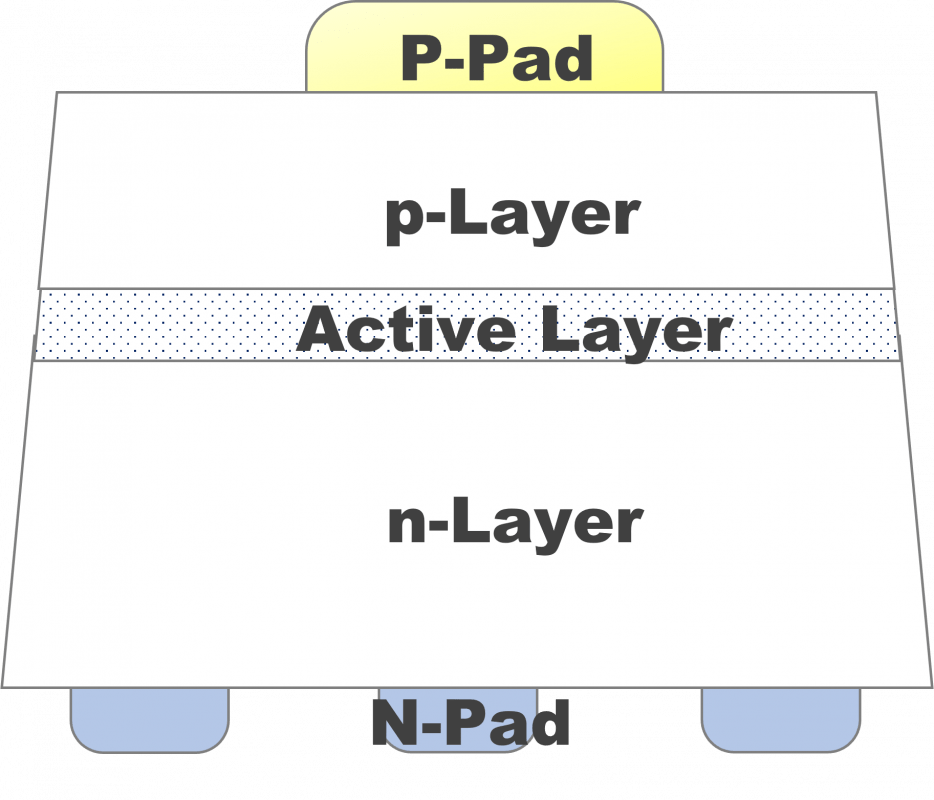
Most of the LED are direct band gap materials and mainly composed of P-type and N-type semiconductors. When a forward bias is externally applied, the holes and electrons flow to N-electrode and P-electrode by electrode field respectively. It will release a certain energy due to electrons and holes recombination at the quantum well. If the energy is released in the form of photons, it will produce the ultraviolet light, visible and infrared light according to different energy gap of materials

High Brightness LED Series (TASC)

These types of LED epitaxy are produced by metal-organic chemical vapor deposition. These kind of products have better optical power (mW) and light intensity (cd) compared to general LED. Thus, the visible light is commonly used in indoor and outdoor decoration light, car exterior and interior, RGB display and Horticulture. The infrared light is for night vision monitor, proximity sensing, eye tracking and wearable in healthcare management.

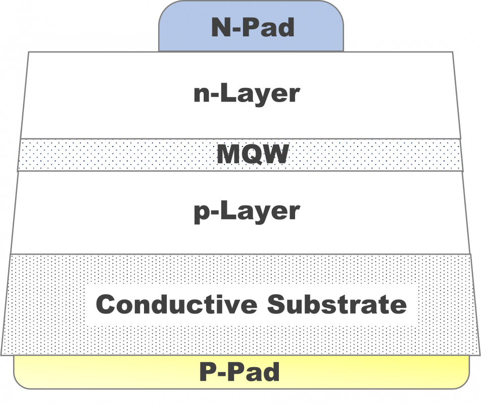
Chip structure

Structure (A)

Structure (B)

Structure (C)

Structure (D)

Parameters Explanation

Dominant wavelength (WLD) : The wavelength which is most closest to vision color of human eye
Peak wavelength (WLP) : The wavelength with highest intensity in light spectrum
Full width at half maximum (FWHM) : The full width of wavelength distance between two points at which the function reaches half its maximum value on spectrum
Radiant Power : The total optical power value per unit time ; The unit is Watt
Luminous Intensity : The illumination of indicated light direction in unit solid angle ; The unit is Candela or cd